On March 1, 2013, director of Preservation and Conservation Richard Kerschner presented our experiences with using LED lighting in exhibition spaces at a one-day symposium held at the Smithsonian American Art Museum's Lunder Conservation Center in Washington, DC. During his case study he shared how we've used LED lighting in the past here, how various departments are involved in choosing the lighting we use, and then Rick talked a bit about the efforts involved in selecting lighting for the new Art and Education Center. Here's his presentation:
This symposium, Gallery Illumination: LED Lighting in Today's Museums, brought together lighting designers, conservators, and scientists to discuss the use of LED lighting in museums. Other presenters included staff members from the National Gallery, London, the National Gallery, Washington, the Minneapolis Museum of Art, the Pacific Northwest Laboratory, as well as the Smithsonian American Art Museum. Clicking on the links in the previous sentence will bring you to their talks.

Showing posts with label Preservation. Show all posts
Showing posts with label Preservation. Show all posts
Tuesday, April 16, 2013

Wednesday, July 11, 2012
How Not To Be Seen
Before:
 And after:
 Contrary to the title, this is not a primer on how to hide oneself a la Monty Python, rather it is about how the Museum carpenters try to make their repairs invisible. In an earlier post I described how I built a brand-new replica of an historic building component, a willful departure from the original materials and appearance; this time I will show you how I rebuilt a door on the Weaving Shed and tried to make it look like I had never been there at all.
The problem at hand was that both doors had sagged downward and were binding on the threshold. A lot of force was needed to get them closed, and as a result the doors were severely racked on a twice daily basis as the building was opened and closed. Constructed of two layers of vertical barn boards nailed (with square nails) to a plywood core, the doors had the structural integrity of a fish's tail and made a similar motion as they moved. The boards had split exactly four feet out from the hinges. Since the doors are five feet wide, and a sheet of plywood is only four, there was a vertical seam in the plywood at this point. This weak point also corresponded to the drip line of the roof:
 Since the doors are open rain or shine (when the Museum is open), the doors were getting a bit punky as a result of periodic watering.
Here I've removed the exterior boards and you can see the awesome fungus growing on the tar paper that covers the doors' plywood core:
 And here you can see that the plywood was rotted as well:
 Note the vertical plywood joint near the right edge: the inner sheathing board had split lengthwise directly over this line. There was tar paper on both sides of the door (under the barn boards): on the exterior to prevent water from penetrating the building; on the interior so the plywood wouldn't be visible through cracks and knot holes. This wood-tarpaper-plywood-tarpaper-wood sandwich trapped and held water from the roof in the middle of the door, hence the fish-tail action.
You're probably thinking, "Hang on a minute, what are modern materials like plywood and tar paper doing on such an old building???"
The Weaving Shed was built in 1955, but it looks much older because it was constructed of old materials the Museum crew salvaged from other structures in the region, leftover parts from other projects, and/or materials that were purchased specifically because they were old and unique (We still have stockpiles of wide barn boards, bricks, square nails, roofing slates, figured hardwoods, etc.) We can only speculate as to the exact time period that this building was intended to represent, but at first glance it looks like it's from the early 19th century. Closer inspection reveals some very contradictory clues...more on that later.
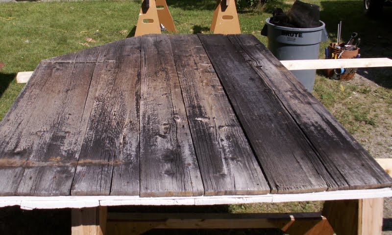
In order to replace the rotten plywood I had to completely disassemble the door. I decided to take the opportunity to make a few design changes. I also made the new plywood core from two pieces, but oriented the seam horizontally. This way the two layers of barn boards would act as battens to hold the door together. The cracked inner sheathing board was 17-inches wide. To get a replacement I dug around in the carpenter shop attic until I got one I liked, ripped it to width and cut it to length (Yes, it was too wide at 18.5 inches!) I laid out the interior boards on my saw horses with the whitewashed inner faces down and glued and screwed the new plywood to them with construction adhesive and short decking screws:

I had attached a strip of Vycor self-adhesive rubberized flashing tape to the top edge of the plywood core, first sticking it to the inner face and leaving the release paper on the rest of the strip. After fastening the plywood to the interior boards I covered the outer face of the plywood with tar paper and lapped the Vycor over the top:
 This way, any water that drips from the roof will run over the Vycor and down the tar paper rather than soaking into the plywood core. I nailed the exterior boards on over the tar paper, again using square nails:
 I then flipped the door over and replaced the square nails in the interior boards. The edges of the door got capped with strips of wood to hide the Vycor and plywood end-grain. The finished door looks like a 100+ year old barn door made of two layers of vertical boards held together by clinched square nails...that it has a structural core of plywood waterproofed with Vycor will be a secret between you and I...
Fixing such damage is only a temporary repair unless the source of the problem is identified and addressed. Therefore I had to do something about the water coming off that roof. There wasn't enough room for a gutter above the door, so I made a sort of inverted drip edge from a sheet of copper with a V-shaped channel on one edge. To install it I removed the first three courses of slate from the roof:
 This was relatively easy because the slates had been installed with slate hooks (usually reserved for repairs) instead of nails. My theory on this: the roofers were concerned about the uneven and flexible nature of the roof sheathing, and couldn't nail the slates for fear of them stressing and breaking over time. The sheathing boards are installed parallel to the rafters (see above), therefore the roof surface is far from flat and flexes a bit when the building is loaded with snow. Normally the sheathing would go horizontally, perpendicular to the rafters, and the slates would sit firmly over any irregularity between sheathing boards. But on the Weaving Shed the roof sags and bounces a lot between rafters, and snow on top would break the slates if they were nailed across an uneven seam, so the roofer used hooks to give the slates a greater degree of stress-free movement. There is a down-side to this method of slating which I'll discuss later. I installed the copper over the cedar shingles that formed the "drip edge", and put back the slates:
 I hosed water onto the roof to test the new diverter and make sure I had it pitched downhill.
 The only discernable change is the fact that the door now easily clears the threshold.
Special thanks to the Museum visitor who stopped to watch me work and ask whether they had Liquid Nails in 1850!


The problem at hand was that both doors had sagged downward and were binding on the threshold. A lot of force was needed to get them closed, and as a result the doors were severely racked on a twice daily basis as the building was opened and closed. Constructed of two layers of vertical barn boards nailed (with square nails) to a plywood core, the doors had the structural integrity of a fish's tail and made a similar motion as they moved. The boards had split exactly four feet out from the hinges. Since the doors are five feet wide, and a sheet of plywood is only four, there was a vertical seam in the plywood at this point. This weak point also corresponded to the drip line of the roof:

Here I've removed the exterior boards and you can see the awesome fungus growing on the tar paper that covers the doors' plywood core:


You're probably thinking, "Hang on a minute, what are modern materials like plywood and tar paper doing on such an old building???"
The Weaving Shed was built in 1955, but it looks much older because it was constructed of old materials the Museum crew salvaged from other structures in the region, leftover parts from other projects, and/or materials that were purchased specifically because they were old and unique (We still have stockpiles of wide barn boards, bricks, square nails, roofing slates, figured hardwoods, etc.) We can only speculate as to the exact time period that this building was intended to represent, but at first glance it looks like it's from the early 19th century. Closer inspection reveals some very contradictory clues...more on that later.
In order to replace the rotten plywood I had to completely disassemble the door. I decided to take the opportunity to make a few design changes. I also made the new plywood core from two pieces, but oriented the seam horizontally. This way the two layers of barn boards would act as battens to hold the door together. The cracked inner sheathing board was 17-inches wide. To get a replacement I dug around in the carpenter shop attic until I got one I liked, ripped it to width and cut it to length (Yes, it was too wide at 18.5 inches!) I laid out the interior boards on my saw horses with the whitewashed inner faces down and glued and screwed the new plywood to them with construction adhesive and short decking screws:


Fixing such damage is only a temporary repair unless the source of the problem is identified and addressed. Therefore I had to do something about the water coming off that roof. There wasn't enough room for a gutter above the door, so I made a sort of inverted drip edge from a sheet of copper with a V-shaped channel on one edge. To install it I removed the first three courses of slate from the roof:


Special thanks to the Museum visitor who stopped to watch me work and ask whether they had Liquid Nails in 1850!
Wednesday, April 11, 2012
Replicating the Work of a Bygone Era: Part 2
I set out to make a new four-foot wide louvered elliptical attic vent for the Variety building, I thought I would have a technological advantage over the original builder, and would have a relatively easy time of it. The original was white pine; I thought redwood would be a more weatherproof material (and we have lots of redwood scrap in the shop from helping Randy repair the Museum's redwood picnic tables). To get the two curved pieces that form the the ellipse I needed a board over seven inches wide, and we didn't have one. Chip had some leftover Atlantic white cedar (Chamaecyparis thyoides), a.k.a Atlantic white cypress, that was wide enough, and equally weatherproof, so I made the frame from that.
 I used the big bandsaw to cut the curves, and a stationary belt sander to smooth them. I copied the mortise-and-tenon joinery from the original, but didn't risk splitting the wood by drilling holes and pegging the delicate joints...I used West System epoxy glue instead. I didn't have a board wide enough to make the bottom rail in one piece. Instead I made a separate piece for the center hub and glued it on with a curved caul (clamping block).
 You can see the dados (slots) to hold the louvers. Before gluing up the new frame I taped the old and new pieces together and traced the location of the dados; I copied the angles with a bevel gauge. To cut them I used a fine-toothed handsaw (I prefer the Japanese style that cuts on the pull stroke), and a narrow chisel fashioned from a sharpened screwdriver. There is no easy way to do this with power tools. There are 81 of these dados on the vent, but working by hand was the only way to do it accurately.
 The louvers were a real challenge: the dados on the center hub were angled about 12 degrees from the face, while the dados on the elliptical frame were angled 45 degrees. This meant the louvers had 33 degrees of twist. In order to twist the new redwood louvers I soaked them in water overnight and then cooked them in a microwave oven on "high" for 5 minutes. Thanks to Mirsad for this idea! Whenever you bend wood it is a good idea to bend it farther than you need, because it will spring back a bit as it dries. I made a bending form with one row of slots at 90 degrees and another at 45, this held the microwaved louvers at 45 degrees of twist until they dried. It is unlikely that the original builder had a microwave oven, but I think he could have done this with steam, or by using green wood.
 It took a day and a half to fit the 40 louvers into the frame. Each one had to have different angles cut on each end, and each one was a different length and taper. I used a block plane to make the ends thin enough to fit snugly in the dados, and used a knife and a plane to taper the louvers flush to (in line with) the frame. Instead of nails I gave each dado a shot of epoxy to hold the louvers in place.
 To make the trim strips that went around the ends of the louvers, I got some western red cedar (Thuja plicata) and Chip's Stanley 45 combination plane, with interchangeable cutters that can produce any shape you need. I needed to make two curved beads, one about twice as wide and tall as the other, but right next to each other.
 I had to bend these strips to the curvature of the ellipse and the center hub, but they were too long to fit in the microwave. I built a steam chamber by attaching the wallpaper steamer from the Conservation Lab to a length of PVC pipe. After an hour of this, the shop smelled like a sauna, and the wood was pliable enough to bend around a curved form.
 I produced a lot of kindling doing this, since the red cedar heartwood wouldn't quite bend far enough without snapping. The sapwood proved to be more flexible. The trim for the center hub was a different matter entirely. I couldn't get the trim stock to bend to such a tight curve no matter how much steaming, soaking, and microwaving; the asymetric double-bead profile made the wood twist every time.
The solution was presented by the original trim pieces, which the carpenter had kerfed (notched) every half-inch to facilitate bending. I did this to a piece of square stock, then soaked and microwaved it. To bend it, I screwed blocks of wood to the ends of a long band clamp, and wedged the trim stock between them. As it bent, the band clamp helped distribute the strain along the wood and prevented it from snapping. Thanks to Chip for this design!
 It took a lot of clamps to attach the trim to the vent until the glued dried. Then it was time to shape the center hub trim.
 The Stanley 45 was too big to make the turn, so I took the cutters out of it and made a "scratch plane" that I could steer more easily.
 The trim pieces moved a lot as I was clamping them, so I made them longer than they needed to be and cut them to length once the glue had set. To avoid gluing the trim where I planned to cut it, I put clear packaging tape on the frame and glued the trim to that. Once it was cut to length, the excess trim could be removed by pulling off the tape. I fashioned the radial pattern on the center hub from redwood scraps, whittling them with a knife and smoothing the lines with a block plane. These got glued on as well.
 Once everything had been glued, shaped, and sanded I submerged the whole unit in a trough of Flood oil and let it soak for an hour. This was less toxic than the original "finish" of creosote and lead paint, and really brought out the color in the cedar and redwood. I stapled brass screen on the back of the vent, and used the Genie lift to install it on the building.

 It is easy to overlook the amount of time and skill required to produce many “architectural details” on old buildings. In this case, a mere attic vent took the better part of three weeks to replicate. While the original builders may have been faster since they weren’t trying to make an exact copy of someone else’s work, they probably did not have power saws, wallpaper steamers, epoxy glue and microwave ovens. While these tools certainly made parts of the job easier and faster, there was no modern substitute for the really important aspects of making delicate pieces of wood fit together well. The bulk of the work was done with saw, chisel, and plane; patience, a steady hand and a true eye—the same way it was done by the carpenter long ago.


The solution was presented by the original trim pieces, which the carpenter had kerfed (notched) every half-inch to facilitate bending. I did this to a piece of square stock, then soaked and microwaved it. To bend it, I screwed blocks of wood to the ends of a long band clamp, and wedged the trim stock between them. As it bent, the band clamp helped distribute the strain along the wood and prevented it from snapping. Thanks to Chip for this design!


Friday, March 23, 2012
Replicating the Work of a Bygone Era: Part 1
How did we go from this:
 To this?
 One of the challenges faced by the Museum carpenters is repairing the many old buildings here, and deciding when to replace, rather than repair something. Sometimes all we have to do is replicate how something was done 150 or more years ago, other times we can better preserve our buildings if we intentionally depart from the original construction. Either way requires careful study of the original to see how it was made, what made it last, and/or what made it fail. The attic vent from the Variety Unit was already severely weathered when squirrels tore through it. There was enough left of the old vent (an elliptical wooden fan) to see how it was made, but there was too much gone or worn out to repair it. I'd be practically rebuilding it, so I set out to make a replacement by copying the appearance of the old one while adding a few improvements. Here's what I learned about the old vent; in Part 2 I'll show you how I made the new one. (A note on scale: this thing is four feet wide, and 20 inches tall).
 Right away I could see a few interesting details: the old vent had big square wrought nails driven through its joints as reinforcement. These were very rusty, and had clearly been in there a long time. The elliptical frame was assembled in halves, with a spline connecting them at the top of the arc. This meant that near the bottom of the arc the grain of the wood cut across the frame at a steep angle to the tenons that held it into the horizontal member--this was prone to splitting. It is easy to imagine that the frame split as it was being assembled, and rather than start over the builder just nailed it back together.
 I could also see where the frame had split around the pegs that held the two halves of the ellipse to the top spline: the splits left dark marks where the spline was exposed to the weather. There were wrought nails all through this joint as well.
 That spline was spiked to the center post, which filled the gap between the two topmost louvers. This meant that it was a three-dimensional wedge, wide at the top and beveled parallel to the louvers, yet thin enough at the bottom to fit between the louvers on the center hub. I think the spline was made from a separate piece because to be strongest its grain needed to be horizontal, yet had it been carved from the same stock used to make the center post the grain would have been vertical, and weak.
 Despite the vintage fasteners used in its construction, the vent was attached to the building with round finish nails. Moreover, the white pine of the vent was much more deeply weathered than the surrounding clapboards and trim. This indicated that although this part of the building was built in the late 1940s, the vent was much older. Close inspection of the vent revealed why it was worth salvaging and re-using: all of its 59 separate pieces had been painstakingly cut and shaped by hand, and were held together by multiple tiny cut nails. The marks of a scratch awl (used to make layout marks instead of a pencil) were still visible, as were the marks of a very thin sawblade and a sharp knife.
 Being hand cut, the elliptical frame was not a regular geometric shape, so each louver had been custom-fitted, with a slightly different length, width, and taper. To make things even more interesting, each louver was slightly twisted (maybe they were steam-bent, or perhaps the builder used green wood?). The louvers were set in narrow dados (slots) in the frame and held in by small nails and a curved trim strip that went all the way around the frame. There was another of these trim strips on the center hub, and in order to bend it to such a tight curve it had been kerfed (cut partway through with a saw) every half-inch, and each segment had a small nail in it.
 The detail on the center hub looked like relief carving from the ground, but it turned out to be made up of thin diamond-shaped slivers that were also nailed on. There were only two left, but I could see the marks left by the others where the hub hadn't been worn down so much by the weather. Each of these was slightly different as well, suggesting they had simply been whittled to shape.
Somebody with a lot of patience spent a long time making this thing!


Wednesday, December 7, 2011
Looking into the Light
Have you been considering using LED (light emitting diode) bulbs for your home or business? This rapidly-developing class of lighting fixture has generated quite a buzz. Since we've been researching and using LED bulbs in some of our galleries for about eight years now, other museums and collectors have been asking us if LEDs might be right for them too.
Finding an exhibition design solution.
So how many museum professionals does it take to screw in a light bulb?
 |
| LED lights have illuminated the dollhouses and cases in the Variety Unit since 2004 |
In 2004 Shelburne Museum installed LED lights in the Variety Unit's doll and scrimshaw cases primarily to solve an exhibition design challenge. While we'd prefer to keep lights out of the cases entirely, it just wasn't possible to light the objects from outside the cases given the relatively low ceilings in this 1835 building. The qualities we were looking for were: no ultraviolet content, low heat and even light. Director of Preservation and Conservation Rick Kerschner looked at a number of options and tested the most promising ones in a mock-up dollhouse room in the Conservation Lab.
If you're interested in the details, he outlined his process in a presentation at the New England Archivists Meeting at Simmons College in 2008, now available as a podcast.
Ultimately, Rick settled on LED bar lights from Prolume. There were several reasons for selecting this company. Their bar-shaped fixture was a size and configuration that met our needs. The small company was also willing to create a light that was the appropriate color (3000 degrees K) and intensity to show off the collections to their best advantage. In addition, Prolume guaranteed that there would be no significant drop-off in the amount of light emitted from these bulbs for 10 years and that the light would not decrease by more than 50% for 15 years. Unfortunately this first generation of LED lights didn't live up to the estimated longevity and lost most of their light after only a few years of use. Prolume honored their guarantee and replaced all of the lights with their third generation LED bar lights containing diodes manufactured by Nichia. These new LED fixtures have been in place for over three years, and we have seen no loss in light intensity.
 |
| Our mock-up dollhouse room with the monitor and some of the lighting options we considered |
Ultimately, Rick settled on LED bar lights from Prolume. There were several reasons for selecting this company. Their bar-shaped fixture was a size and configuration that met our needs. The small company was also willing to create a light that was the appropriate color (3000 degrees K) and intensity to show off the collections to their best advantage. In addition, Prolume guaranteed that there would be no significant drop-off in the amount of light emitted from these bulbs for 10 years and that the light would not decrease by more than 50% for 15 years. Unfortunately this first generation of LED lights didn't live up to the estimated longevity and lost most of their light after only a few years of use. Prolume honored their guarantee and replaced all of the lights with their third generation LED bar lights containing diodes manufactured by Nichia. These new LED fixtures have been in place for over three years, and we have seen no loss in light intensity.
 |
| Note the differences in color among the first generation LEDs (top) versus the third generation LEDs (bottom). The diodes on the bottom are more uniform in color in contrast to the lights on the top. Its subtle, but it makes a difference. |
In fall, 2010, Efficiency Vermont offered the museum a sweet deal - a full rebate on all the LED lights we cared to purchase (but only until December 31, 2010)! While conservators love free stuff just as much as anyone else, there were questions about the nature of the light emitted by LED lamps as compared to the more commonly used incandescent and halogen lights. We needed to know whether the light generated from the LEDs would be any more damaging than the light generated by the halogen lamps we were used to. Additionally we wondered if commercially available LED lights had the same color and intensity consistency that Rick had been only able to achieve for the Variety Unit cases by working directly with the manufacturer.
So as other institutions, including the National Gallery in London and the Getty Conservation Institute, were looking at commercially available bulbs in their labs to determine how the nature of light generated by an LED compared to fluorescent and incandescent lamps, Rick did some practical research in our galleries. He mocked up up comparisons and showed them to the electrician, exhibit designer, curators, director, and anybody else who had an interest in how the buildings were lit. Although Rick paid close attention to the color rendering index (CRI) of the LEDs, in the end, what was most important was how the artifacts actually appeared under the lights. Informed by the research done at other institutions and our own mock-ups, Shelburne Museum staff decided that the Philips EnduraLED MR16 and Sylvania UltraLED PAR 20 and PAR 30 LED replacement bulbs worked best for responsibly displaying our collections in our buildings with low ceilings.
Rick Kerschner, Exhibit Preparator Doug Oaks and Electrician Rick Gage have been generally pleased with the performance of these bulbs over the 2011 season. In total Shelburne Museum received over $50,000 worth of bulbs through Efficiency Vermont's "free LED" program. Rick estimates the yearly energy savings to be about $6,000; so payback will take about 10 years. Although the bulbs are rated for about 40,000 hours (or slightly more than 32 Shelburne Museum seasons) Rick is not convinced they will last that long. It remains to be seen how cost effective these bulbs really are.
More links to sources of information about using LEDs for exhibition lighting can be found on the American Institute for Conservation's website and within the LinkedIn Museum and Art Gallery Lighting discussion group. The Getty Conservation Institute's Guidelines for Selecting Solid State Lighting for Museums is available on request from their website.
Wednesday, September 28, 2011
Caring for your Heirloom Quilts
We get inquiries in the conservation lab fairly often about how to hang heirloom quilts. Director of Preservation and Conservation Rick Kerschner wrote up these suggestions a few years ago and we've been distributing them on request.
Displaying quilts
I have a few cautions about mounting quilts
on the wall. Once a quilt is mounted on the wall, it tends to stay up for a
long time. Most textile conservators recommend limiting exhibition to 6 months
to a year. At Shelburne, we take our quilts down every few years (we are only open
6 months a year) and rotate new ones onto display. I would encourage homeowners
to also implement some reasonable schedule to rotate a quilt back to storage
for at least an equal amount of time that it is being displayed. In general, we prefer to cover
our quilts with Lexan (polycarbonate), Mylar, or Melinex whenever possible to
protect them from dust and handling. I am sure that you probably have good filters on your furnace to
filter out dust, but dust that is kicked up from the floor that never makes it
into the HVAC system can still be a problem. For that reason, I would recommend
that the bottom of the quilt be at least 2 feet above the floor.

Cleaning a quilt that has been hanging
1.Obtain a piece of plastic window screen and bind the edges so that they will not snag the textile.
2. Lay quilt flat.
3. Place the window screen on top of the quilt and, using a brush attachment on a HEPA vacuum with suction control set to low suction, vacuum both sides of the quilt. Avoid rubbing the brush attachment against the screening.

Vacuuming a quilt through a screen
Light and your quilt
Be sure to mount the quilt away from
daylight, not just out of direct sunlight from a window, but away from any
significant window light. Actually, the highest light levels are recorded in a
home during the winter when the sun is low in the sky and can shoot in windows,
and when there is snow on the ground to reflect the light into the house.
Daylight will fade certain dyes on antique quilts very quickly, and can cause deterioration to fibers on fabrics that contain metal based mordants (iron-based mordants are found in brown-dyed cotton fabrics of the late nineteenth century). It is fine to light the quilt with track lights, but they
should be mounted well back from the quilt (about 5 feet) and low wattage wide
floods should be used to illuminate it (35 to 50 watt tungsten floods are best
- the old fragile looking frosted kind, not the newer halogen lights, as they
have too much UV radiation). If you can feel any heat on the back of your hand
when it is held in front of the quilt, the lights are too close. It is better
to try to get a low, even light on the entire quilt using several floods than
to use one or two bright halogen bulbs and have too much light in some areas
and a spotty appearance. It would be best if the light track could be on a
separate switch so that it can be turned off without making the entire room
dark.
Check with a conservator in your area for additional advice and ask to have light levels measured for the final installation. A conservator can be
located through the American Institute for Conservation Referral Service.
Displaying quilts
Finally, there are other ways to display
heirloom quilts:
1. Lightly folded at the bottom of a bed
2. Draped over a wide tube (6" diameter or more) mounted parallel to the wall (this displays half the quilt at a time and the quilt can be easily turned so that the other side is exposed to the "elements." No Velcro or other mounting mechanisms are required for this display method).
3. Very fragile and precious quilts are usually lightly folded in long and narrow acid-free storage boxes that can be stored under a bed or on a high closet shelf and brought out only occasionally for special guests.
There are a number of other good resources on caring for heirloom textiles available on the internet. In particular, there are good general guides to caring for textiles on the American Institute for Conservation's website and the Textile Museum's website. The Philadelphia Museum of Art shares some of their techniques for storing historic garments and accessories on their site and the Minnesota Historical Society shares their tips for storing flat textiles in boxes.
Tuesday, May 10, 2011
The Bazzoni Doll Goes to the Hospital
It must have been a beautiful doll once, with lifelike translucent skin of wax on a molded papier mâché core and realistic glass eyes with brown threaded irises rimmed in purple.

Due to light exposure and variations in temperature and humidity, the paint and wax coatings on the doll's face have faded, split, and chipped. A wig, once held by straight pins was not present when the doll entered museum founder Electra Webb's collection. This doll, looking something like spawn of Pinhead from the Hellraiser movies, is a poor representation of what it once was.


So why is it in Shelburne Museum's collection, you ask?
This doll, made sometime around 1850, is the only known remaining example of the work of London wax and composition doll maker Anthony Bazzoni. His printed mark is found above the doll's hips. Rarely did wax doll makers from this period sign their work. While this doll has no internal mechanisms, Bazzoni is celebrated as one of the first makers to create a talking doll. The eyes were not made by Bazzoni, but by another specialist craftsman. According to Henry Mayhew's book London Labour and the London Poor (1851), there were two dolls-eyes makers working in London when this doll was produced. These craftsmen made artificial eyes for humans, too. As the only known example of Bazzoni's work, this doll could be considered a type specimen, a term coined in biology for a physical example, usually held in a museum, that defines a species.
Fletcher Allen Health Care, Vermont's university hospital and medical center, lent a hand in our efforts to document how this doll was made by taking x-ray images and computerized tomography (CT) scans.

The radiograph shows that a fairly coarse paper pulp was used in the mold. The outlines of the pulp wads are evident through the cheeks and temples in the image. The apparent texture of the paper is consistent with Mayhew's description of the re-purposing of the coarse blue paper bags used to package sugar during that period. The pins that once held the wig are inserted behind the eyes, not into them, as it appears here. You get a sense of the globe-shaped eyes.

The images from the CT scan show us the doll in cross section and a whole lot of features that we couldn't see in the radiographs: how thin the papier mâché core is and the shape of the eyes. We see that the eyes were free-blown given the slight variations in shape and the presence of the flanges where the blow tube had been attached at the back.

Among the things the CT images from the body show is that the stitching that holds the cloth body closed under the head is in good condition, but the seam appears to be a bit open, explaining why some sawdust is loose in the doll's storage box.

So in addition to learning more about how this doll was made, I learned a bit more about its condition without having to take it apart. We really appreciate the time the radiological techs took to produce these images. I hope they enjoyed looking at something that wasn't human. (The tech did try to input the doll's date of birth in the system, but the computer wouldn't take it.)
After almost 10 years in storage, we're bringing this doll back on view, along with the x-ray, in the Conservation exhibition in one end of the Circus Building. If you'd like a closer look at any of these images, take a look at the Bazzoni doll's set on Flickr.
Thursday, April 7, 2011
Tales (Tails?) of Two Carousels
I spend a fair amount of time talking about the museum's 1902 Gustav Dentzel Company carousel, quite a rarity in that all decorative elements were acquired together and had never been repainted in its working lifetime. The carousel was originally commissioned by the Fonda, Johnstown, and Gloversville railroad for their end-of-the-line amusement park on the Sacandaga River.
Most of the decorative elements of this carousel have been on display at the museum as examples of the carousel carver and painter's craft since the 1960's. But the painted wood elements, such as the horses, swan boat and giraffes, had been coated with linseed oil as a maintenance procedure for about twenty years here at the museum.
Since 1985, a total of twenty-seven interns studying conservation, hailing from five countries, have come to Shelburne Museum to remove dirty, darkened linseed oil from the painted surfaces of the menagerie, and rounding boards from this carousel, Since 2003, these internships have been funded through an Adopt-a-Carousel initiative. In return for funding an intern's stipend, donors have the honor of choosing and naming a carousel animal that intern will work on. This June a twenty-eighth intern will join us for eleven weeks to clean the 31st animal of the 40 animal menagerie and one of the rounding boards.
My colleagues and I have written articles for the conservation literature about how our cleaning protocols for these animals have developed over the years, created slide shows of the treatment process on Flickr, and administrate a Facebook page to share the carousel's history and updates of our progress.
Well, its high time that I filled you in on the behind-the-scenes action regarding the other carousel - the one that sits in front of the Circus building. Made around 1920 by the Herschell-Spillman Company of North Tonawanda, New York, this model was designed to be disassembled and reassembled for use in a traveling carnival. Unlike the Dentzel carousel, the Herchell-Spillman came to the museum stripped of its original factory paint and was later coated in bright colored "park paint". In contrast to the Dentzel carousel, this one retains every part of its original function. Each fall, members of the Buildings and Grounds departments disassemble the carousel for winter storage and every winter the Buildings department repairs and repaint a number of horses so that museum visitors can fully enjoy this vintage carousel come spring.

Parts of the Herschell-Spillman carousel stored for the winter
Painter Justin Mayo is in his fourth year here at the museum and in that time he's worked on every horse and the two chariots on the Herschell-Spillman. I talked to him a bit about the horse he's currently working on, one that he worked on his first winter on the job.


When this horse came into the paint shop, Justin noted that the carved wood tail was really wobbly. On closer inspection he found that it was only being held in place with a few long nails into a mass of wood filler and deteriorated wood within the horse's body. Working with Chip Stulen, who directs the Buildings department, Justin and Chip made the tail more stable by removing the old repair and replacing it with a carved wood plug. A dowel connects the tail with the repaired sections within the body. Gaps are then filled and primed and the horse will be repainted.
This horse tail should be better able to withstand the demands of use. Contrast that wooden tail with the 109 year old horsehair tails on the Dentzel carousel horses which don't withstand much handling at all.
Similar to the reports we keep on the work we do in the conservation lab, Justin keeps a notebook which contains images of each horse and chariot when it entered the museum in the 1980's as well as a log of the work that's done on each horse. He records the paint colors used and what repairs were undertaken so that we have a record of who did what and when. This helps him to match paint colors across the animals, presenting a cohesive appearance, and to prioritize work for the next winter.
In short, what underlies our work is the same. We each aim to preserve a carousel that you and your families can enjoy, albeit in slightly different ways.
Monday, February 7, 2011
Art Conservation at Shelburne Museum: the exhibition
Three years ago, we opened a small exhibition on art conservation as practiced here at Shelburne Musem at one end of the Circus Building. It was curated by director of Preservation and Conservation Rick Kerschner, Conservation Fellow Rachel Penniman, and me and funded by the Institute for Museum and Library Services as part of a grant to undertake conservation treatment on the decorative panels and organ from the museum’s 1902 Dentzel carousel.
In addition to showing a number of pieces from the carousel in the process of being cleaned and restored, we focused on some of the things that we do in exhibition buildings to prevent the works of art and artifacts from deteriorating, using Circus Building’s environmental control and monitoring systems as an example. Panels in the show explained what kind of training you need to become an art conservator and where you can go on the internet for more information. If you missed it, here are pictures of the installation taken by Daniel Cull, a colleague who visited during the summer of 2009:
We noticed that visitors were quite drawn to one corner of the show where we had a video from WCAX on how Rachel and her fellow Fellow Laura Brill removed a discolored coating from the painted surfaces of the Dentzel carousel's swan chariots.
While the video and exhibition were a good introduction to what we do, there are other aspects of our work that we want to share. We also noticed that some parts of the exhibition worked better than others. Building on that experience, a new version of the exhibition will be on view this season. You’ll be able to examine a painting with condition problems using various lighting techniques, just like we do in the lab, and experience how we characterize various kinds of materials using ultraviolet light.
What questions do you have about art conservation? What would you like to see in an exhibition about the Conservation Department’s work at Shelburne Museum?
Subscribe to:
Posts (Atom)